



RTD sensors are widely used in industrial temperature measurement systems because of their high accuracy, stability, and long service life. However, correct wiring plays a critical role in ensuring accurate temperature readings.
Many users search for RTD probe wiring because incorrect connections can cause measurement errors, unstable signals, or inaccurate temperature monitoring.
Depending on application requirements, RTD sensors can use different wiring configurations, including 2-wire RTD, 3-wire RTD, and 4-wire RTD wiring. Each method has different accuracy levels and application advantages.
This guide explains how RTD probe wiring works, the differences between wiring methods, and how to choose the right connection for PT100 and PT1000 temperature sensors.
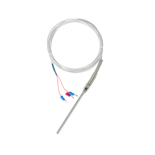
What Is RTD Probe Wiring?
RTD probe wiring refers to the electrical connection method between an RTD Temperature Sensor and a temperature measurement device, such as a temperature controller, transmitter, or data acquisition system.
An RTD (resistance temperature detector) measures temperature by detecting changes in electrical resistance. As temperature changes, the resistance value of the sensing element changes accordingly.
Common RTD sensors include:
PT1000 temperature sensors
Industrial RTD probes
Stainless steel RTD probes
Thin film RTD sensors
The wiring configuration affects measurement accuracy because the resistance of connecting wires can influence the final temperature reading.
How Does an RTD Sensor Work?
An RTD sensor works based on the principle that the electrical resistance of certain metals changes predictably with temperature.
The most common RTD material is platinum because it provides:
Excellent stability
High accuracy
Wide temperature range
Long-term reliability
For example:
PT100: 100 ohms resistance at 0°C
PT1000: 1000 ohms resistance at 0°C
During operation:
The measuring device sends a small electrical current through the RTD element.
The RTD resistance changes according to temperature.
The system calculates temperature based on resistance variation.
Different Types of RTD Probe Wiring Configurations
There are three common RTD wiring methods:
2-wire RTD wiring
3-wire RTD wiring
4-wire RTD wiring
The main difference between these configurations is how they compensate for lead wire resistance.
2-Wire RTD Wiring
What Is a 2-Wire RTD?
A 2-wire RTD is the simplest wiring configuration. It uses two wires connected directly to the sensing element.
Advantages of 2-Wire RTD Wiring
Simple installation
Low cost
Easy maintenance
Suitable for short-distance applications
Disadvantages of 2-Wire RTD Wiring
The main limitation is accuracy. Because the resistance of lead wires is included in the measurement, errors may occur.
Long cables increase resistance error
Temperature changes affect cable resistance
Measurement accuracy decreases
Applications of 2-Wire RTD
Basic temperature monitoring
Short cable installations
Low-cost industrial applications
3-Wire RTD Wiring
What Is a 3-Wire RTD?
A 3-wire RTD is the most commonly used RTD wiring method in industrial applications. It adds an additional wire to compensate for lead resistance.
Advantages of 3-Wire RTD Wiring
Better accuracy than 2-wire systems
Compensation for lead resistance
Good balance between cost and performance
Widely supported by industrial controllers
Applications of 3-Wire RTD
HVAC systems
Process control equipment
Industrial automation
Temperature monitoring systems
Most industrial PT100 wiring applications use the 3-wire configuration.
4-Wire RTD Wiring
What Is a 4-Wire RTD?
A 4-wire RTD provides the highest measurement accuracy by completely eliminating lead wire resistance effects.
It uses:
Two wires for supplying current
Two wires for measuring voltage
Advantages of 4-Wire RTD Wiring
Highest accuracy
Excellent stability
No lead resistance error
Ideal for precision measurement
Applications of 4-Wire RTD
Laboratory equipment
Calibration systems
Precision temperature measurement
Research applications
RTD Wiring Diagram Comparison
| Wiring Type | Number of Wires | Accuracy | Cost | Common Applications |
|---|---|---|---|---|
| 2-Wire RTD | 2 | Low | Low | Basic temperature monitoring |
| 3-Wire RTD | 3 | Medium-High | Medium | Industrial control systems |
| 4-Wire RTD | 4 | Highest | Higher | Precision measurement |
PT100 Wiring vs PT1000 Wiring
PT100 Wiring
PT100 sensors have a resistance of 100Ω at 0°C and are commonly used in industrial temperature measurement applications.
Common wiring methods include:
2-wire PT100
3-wire PT100
4-wire PT100
PT1000 Wiring
PT1000 sensors have a resistance of 1000Ω at 0°C and provide higher resistance output, reducing the influence of lead resistance.
PT1000 sensors are commonly used in:
HVAC systems
Electronic temperature controllers
Energy management systems
Common RTD Probe Wiring Problems
1. Incorrect Wire Connection
Incorrect wiring may cause:
Incorrect temperature readings
Sensor failure alarms
Unstable signals
2. Cable Resistance Error
Long cables can introduce additional resistance. Recommended solutions include:
Using 3-wire or 4-wire RTD configurations
Selecting suitable cable specifications
Reducing unnecessary cable length
3. Poor Electrical Contact
Loose connections may create unstable readings.
Recommended practices:
Use reliable terminals
Check connector quality
Protect connections from moisture
How to Choose the Right RTD Probe Wiring Method?
1. Required Accuracy
Basic monitoring → 2-wire RTD
Industrial measurement → 3-wire RTD
Precision measurement → 4-wire RTD
2. Cable Distance
Short distance: 2-wire RTD may be acceptable
Long distance: 3-wire or 4-wire RTD is recommended
3. Application Environment
Consider:
Temperature range
Vibration conditions
Moisture exposure
Installation space
Correct RTD probe wiring is essential for achieving accurate and stable temperature measurement. While 2-wire RTDs provide a simple and economical solution, 3-wire RTDs offer a better balance between cost and accuracy, making them the most common choice for industrial applications.
For precision temperature measurement, 4-wire RTD wiring provides the highest accuracy. Understanding the differences between 2-wire, 3-wire, and 4-wire RTD sensors helps engineers select the right temperature sensing solution for different applications.
FAQ About RTD Probe Wiring
What is the difference between 2-wire and 3-wire RTD?
A 2-wire RTD does not compensate for lead resistance, while a 3-wire RTD uses an additional wire to reduce measurement errors.
Why does RTD use 3 wires?
A 3-wire RTD uses an extra wire to compensate for connecting cable resistance and improve measurement accuracy.
How do you wire a PT100 sensor?
A PT100 sensor can use 2-wire, 3-wire, or 4-wire wiring depending on accuracy requirements. Industrial applications commonly use 3-wire PT100 wiring.
Which RTD wiring method is the most accurate?
A 4-wire RTD provides the highest accuracy because it eliminates lead wire resistance errors.
