



A pt100 temperature sensor is a resistance temperature detector (RTD) widely used for accurate temperature measurement in industrial equipment, automation systems, process control, HVAC systems, and other applications. If a PT100 sensor provides an incorrect temperature reading, testing its resistance is one of the simplest ways to determine whether the sensor is working properly.
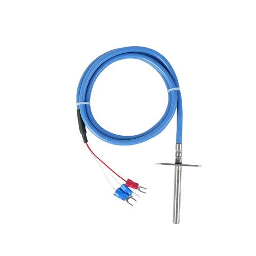
This guide explains how to test a PT100 temperature sensor using a multimeter, how to check different wiring configurations, how to compare measured resistance with standard values, and how to identify common PT100 sensor problems.
What Is a PT100 Temperature Sensor?
A PT100 is a platinum resistance temperature sensor with a nominal resistance of 100 ohms at 0°C. Its electrical resistance changes predictably as temperature changes, allowing temperature to be determined by measuring the sensor's resistance.
Unlike thermocouples, which generate a small voltage related to temperature, a PT100 works by changing its electrical resistance. This makes resistance measurement an important part of PT100 temperature sensor testing.
PT100 sensors are commonly available in 2-wire, 3-wire, and 4-wire configurations. The wiring configuration affects measurement accuracy, especially when the sensor is connected to a long cable.
What Tools Do You Need to Test a PT100 Sensor?
Basic PT100 testing does not require complicated equipment. For a simple resistance test, you will normally need:
A digital multimeter with resistance measurement
The PT100 temperature sensor being tested
Test leads or probes
A known temperature environment
A PT100 resistance-temperature table
For more accurate testing, a calibrated temperature source, RTD calibrator, or precision resistance measurement instrument can be used.
How to Test a PT100 Temperature Sensor with a Multimeter
The basic method for testing a PT100 is to measure its resistance and compare the measured value with the expected resistance at the known temperature.
Step 1: Disconnect the Sensor
Before measuring resistance, disconnect the PT100 from the temperature controller, PLC, transmitter, or other measuring equipment. Testing a sensor while it is connected to an active circuit may produce inaccurate readings and can potentially damage equipment.
Step 2: Set the Multimeter to Resistance Mode
Set the digital multimeter to the resistance measurement function, usually marked as Ω.
Select an appropriate resistance range if the multimeter does not automatically select the range. Because a PT100 has approximately 100 Ω at 0°C, a low-resistance measurement range is normally appropriate.
Step 3: Identify the Sensor Wires
Determine whether the PT100 is a 2-wire, 3-wire, or 4-wire sensor. The wire arrangement is important because each configuration uses a different measurement method.
Step 4: Measure the Resistance
Place the multimeter probes across the appropriate sensor wires and record the resistance value.
The measured resistance should correspond approximately to the actual temperature of the sensing element. For example, a standard PT100 should measure approximately 100 Ω at 0°C.
Step 5: Compare the Reading with the Expected Value
Compare the measured resistance with a standard PT100 resistance-temperature table. A small difference may be caused by measurement accuracy, lead resistance, sensor tolerance, or environmental temperature.
PT100 Resistance vs. Temperature
A standard PT100 has a resistance of 100 Ω at 0°C. As temperature increases, the resistance also increases.
| Temperature | Approx. PT100 Resistance |
|---|---|
| 0°C | 100.00 Ω |
| 10°C | 103.90 Ω |
| 20°C | 107.79 Ω |
| 25°C | 109.73 Ω |
| 30°C | 111.67 Ω |
| 50°C | 119.40 Ω |
| 100°C | 138.51 Ω |
The exact resistance depends on the applicable RTD standard, sensor tolerance, and temperature. For precision testing, use the manufacturer's resistance table or the applicable standard rather than relying only on approximate values.
How to Test a 2-Wire PT100
A 2-wire PT100 is the simplest configuration to test. The two wires are connected directly to the sensing element.
Set the multimeter to resistance mode and connect one probe to each wire. The measured resistance represents the resistance of the PT100 element plus the resistance of the connecting wires.
This means that cable resistance can introduce an error, especially when the sensor is installed far away from the measuring instrument.
How to Test a 3-Wire PT100
Three-wire PT100 sensors are widely used in industrial temperature measurement because the wiring configuration can compensate for much of the lead resistance.
When testing a 3-wire PT100 with a multimeter, first identify the three wires. Typically, two wires connected to the same side of the sensing element should have very similar resistance to the third wire when measured individually.
Exact wire colors are not universal, so the wiring diagram supplied by the manufacturer should be used whenever possible.
How to Test a 4-Wire PT100
A 4-wire PT100 provides the highest measurement accuracy among the common RTD wiring configurations because the measurement circuit can largely eliminate the effect of lead resistance.
Two wires are generally used to supply the measurement current, while the other two wires measure the voltage across the sensing element.
For basic troubleshooting, a multimeter can be used to verify continuity and approximate resistance. For precision calibration, a dedicated RTD measurement instrument or calibrated resistance measurement system is recommended.
How to Check Whether a PT100 Sensor Is Faulty
Resistance measurement can help identify several common PT100 problems.
1. Infinite Resistance
If the multimeter displays OL, infinite resistance, or another open-circuit indication, the sensing element or wiring may be broken.
2. Extremely Low Resistance
A reading close to 0 Ω may indicate a short circuit in the sensor or wiring. Check the connections and sensor element before replacing the sensor.
3. Resistance Does Not Match Temperature
If the resistance is significantly different from the expected value for the actual temperature, the sensor may be damaged, incorrectly wired, or outside its specified tolerance.
4. Unstable Resistance
If the resistance fluctuates significantly while the sensor and temperature remain stable, inspect the sensor wires, terminals, connectors, and sensing element for loose connections or damage.
How to Test PT100 Accuracy
A resistance check confirms whether a PT100 behaves approximately as expected, but it does not by itself constitute a complete calibration.
To evaluate sensor accuracy, place the PT100 in a controlled temperature environment and compare its measured temperature or resistance with a calibrated reference.
For example, the sensor can be tested at several temperature points rather than at only one point. This helps identify whether the sensor maintains acceptable accuracy throughout its operating range.
For industrial applications requiring high accuracy, testing should be performed using calibrated equipment and documented procedures.
Common PT100 Testing Mistakes
Several simple mistakes can lead to incorrect conclusions when testing a PT100 temperature sensor.
Testing the sensor while it is still connected to an active circuit
Ignoring lead resistance when testing a 2-wire PT100
Using the wrong wiring configuration
Comparing the measured value with an incorrect resistance table
Not allowing the sensor to reach a stable temperature
Holding the sensing element with bare hands during a low-temperature test
Ignoring loose terminals or damaged cables
Assuming every PT100 uses the same wire color convention
PT100 Testing Checklist
When troubleshooting a PT100 temperature sensor, the following basic sequence can help:
Disconnect the PT100 from the measurement circuit.
Identify whether it is a 2-wire, 3-wire, or 4-wire sensor.
Set the multimeter to resistance mode.
Measure the resistance between the appropriate wires.
Check for open circuits or short circuits.
Determine the actual sensor temperature.
Compare the resistance with the correct PT100 resistance table.
Inspect the cable, terminals, and connectors.
Perform a controlled temperature test if higher accuracy is required.
Frequently Asked Questions
What resistance should a PT100 have at room temperature?
At approximately 20°C, a standard PT100 has a resistance of about 107.79 Ω. At 25°C, the resistance is approximately 109.73 Ω. The exact value depends on the actual temperature and the applicable RTD standard.
Can I test a PT100 with a multimeter?
Yes. A digital multimeter with resistance measurement can be used for basic PT100 temperature sensor testing. It can help identify open circuits, short circuits, and resistance values that are significantly outside the expected range.
How do I test a 3-wire PT100?
Identify the three wires and measure the resistance between the different wire pairs. The exact testing method depends on the sensor's wiring configuration, so the manufacturer's wiring diagram should be consulted when available.
Why does my PT100 show the wrong temperature?
Possible causes include incorrect wiring, lead resistance, sensor damage, loose connections, incorrect transmitter settings, unsuitable calibration, or a mismatch between the sensor and the measurement instrument.
How do I know if my PT100 is broken?
An open circuit, a near-zero resistance reading, unstable resistance, or a resistance value that is significantly inconsistent with the actual temperature can indicate a problem. The sensor and wiring should be checked before determining that the sensing element itself has failed.
Learning how to test a PT100 temperature sensor is useful for both routine maintenance and troubleshooting. The simplest method is to disconnect the sensor, measure its resistance with a multimeter, and compare the result with the expected PT100 resistance at the known temperature.
For basic troubleshooting, this method can quickly identify open circuits, short circuits, wiring problems, and abnormal resistance. For applications requiring higher accuracy, a controlled temperature test with calibrated equipment should be used.
Understanding the differences between 2-wire, 3-wire, and 4-wire PT100 sensors is also important because wiring configuration can affect measurement accuracy. By following the correct testing procedure and using the appropriate resistance-temperature reference, users can more effectively evaluate the condition and performance of a PT100 temperature sensor.
